Update and some tips for the Team Associated RC12L3 (part 1). |
|
Edité le 07/12/2007. |
Second part. |
|
|
Pour la version française, cliquez sur l'image ci-contre. |
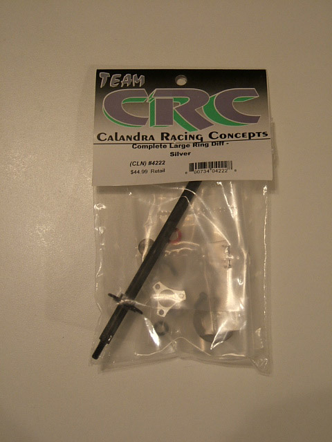
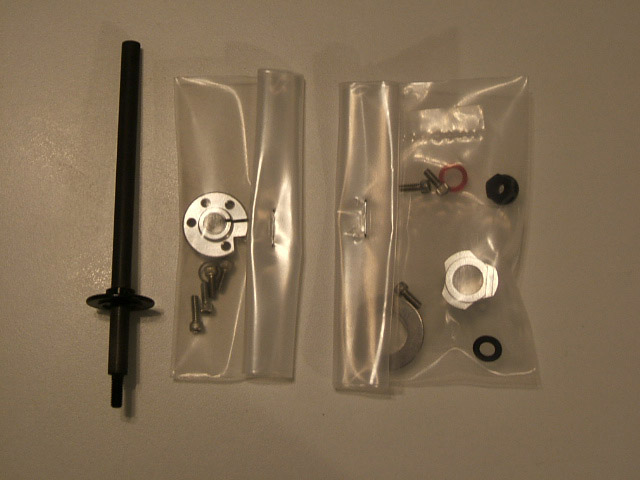
IntroductionThe following lines deal with an update and some tips applied on a Team Associated RC12L3. Why updating an at least 4/5 years old car? There are many reasons such as cost, low/poor driver skill, performance on the car. As the owner of this car is re-entering RC after some years off, entering 1:12 scale car and never drove a pan car before, purchasing a used car was considered as a good reasonable choice looking at the cost of a brand new car compared with potential damage the car will suffer. It could have been a Team Associated RC12L4, a Team CRC Carpet Knife V3.2R or a Team Corally SP12M available on the market of used RC cars, but the opportunity was this one, with - as many US produced car - a high upgrade potential. As this car is almost stock - some none genuine screws and servo mounts - and unprepared (rough edge chassis), it was a good base to also learn things and applying some techniques of preparation. Differential & rear axleAs a 4/5 years old car, the RC12L3 got a differential with small differential's plates. The most recent products - Team Associated RC12L4, Team CRC Carpet Knife V3.2R, Team Corally SP12X, Team Speed Merchant Rev 5, BMI Racing DB12R, Hot Bodies Cyclone 12, naming here maybe half of the actual production - got a large plates. To update this area of the car, Team CRC can provide a solution with a whole set of parts, #4222 - complete large ring diff. This product contains a rear axle, left and right hub carrier, two large diff rings, a lock nut, six wheel screws, a Belleville spring, two 0.15" spacers and 3mm thick thrust spacer. Diff balls and a spur gear were the only things to add, as well as diff grease. |
 |
 |
|
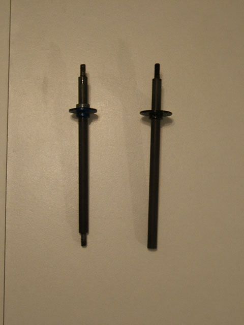
To assemble all those components, no things difficult at it is explained in various places, car manuals and websites. Team CRC Generation X manual were use here as well as some advice of this website and again a dedicated page by CRC. Pictures show some difference between the original differential (left) and the replacement item (right). The RC12L3 rear axle got a screw on the left hand side as the CRC axle is fully round. The screw on the Associated parts is used to mount the left hub, as it will be clamped on the CRC one. |
 |
 |
|
To improve the behavior of this differential and for engineering purpose relative to the design of the differential, a thrust bearing was also purchased. The aim is to get a longer running differential. The original design loads axially a ball bearing. Mechanically speaking, that's possible but the axial load tend to wear quickly the bearing and it will need to be change more often. In fact, this point is just to do things as the mechanical principal ask to do. Items purchased:
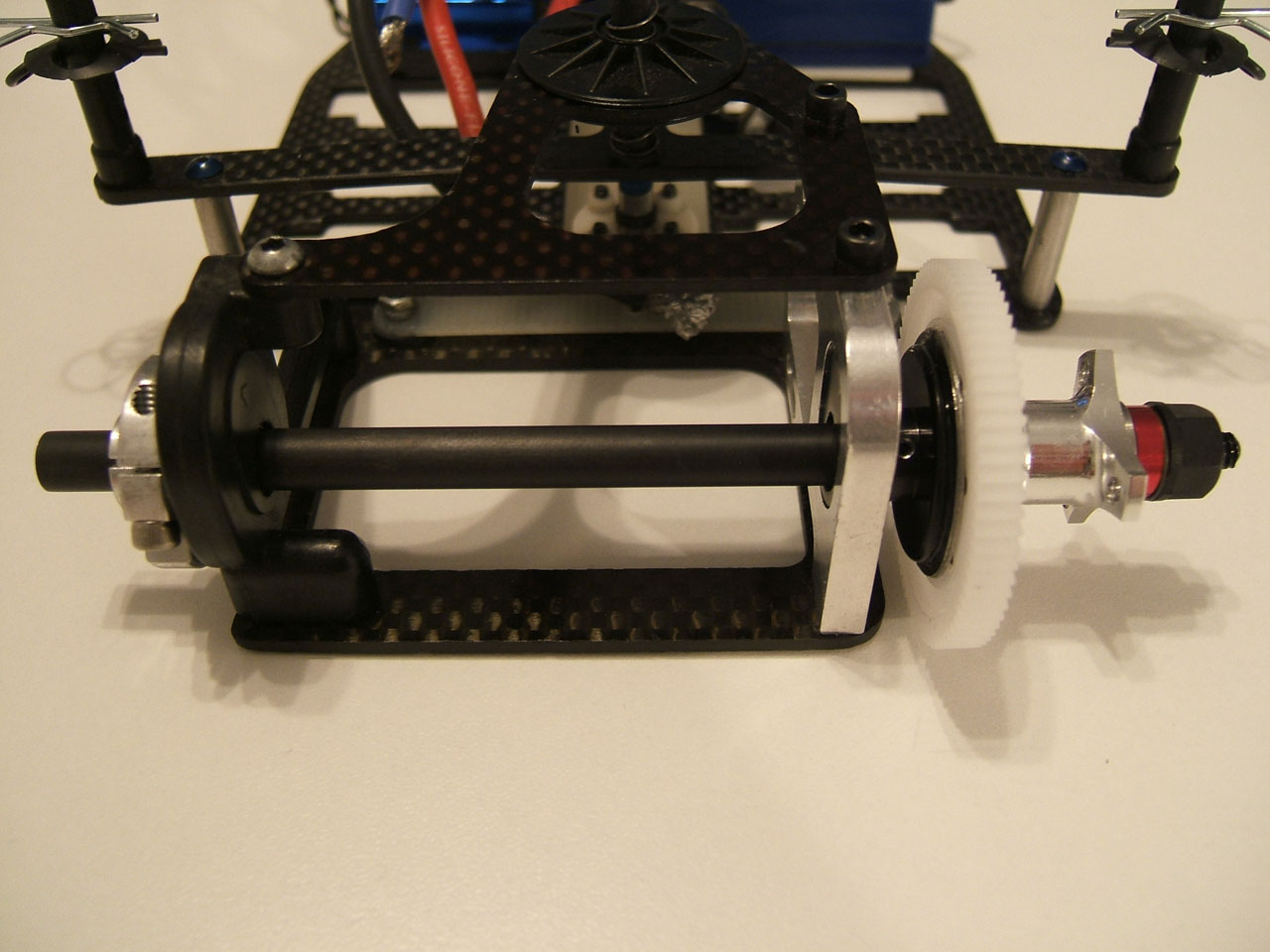
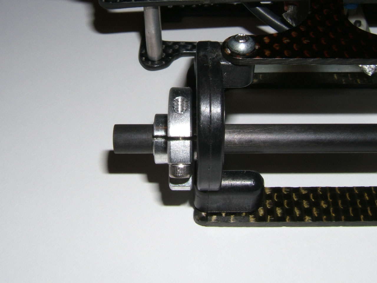
The first step was put all parts tougher and the following pictures show the result without the thrust bearing. The assembly is straight forward, adjusted with four shims, two on each side on first instance. The number of shim is a setup parameter as that will wider or narrower the rear end. |
 |
 |
 |
|
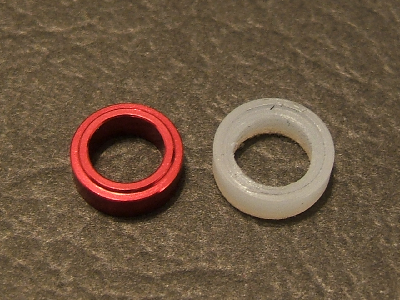
The second move was to install the thrust bearing. To do so, the spacer (red part) need to be removed and replaced by a similar one with a larger external diameter and the lip on the larger (outer) diameter. The original CRC part got the following dimensions:
The replacement part got the same inner diameter, the outer diameter increase slightly to reach 10.5mm - the same diameter as the external ball bearing's ring, the thickness still the same. The replacement part is a custom part, there is no possibility to purchase it directly. Slapmaster Tools makes this type of spacer but the dimensions are maybe different (larger inner diameter). This part can be made with the help of a true, the material used is a standard Nylon 4-6 or 6-6 (Polyamide 4-6 or 6-6), non-reinforced with fiber. |
 |
 |
 |
|
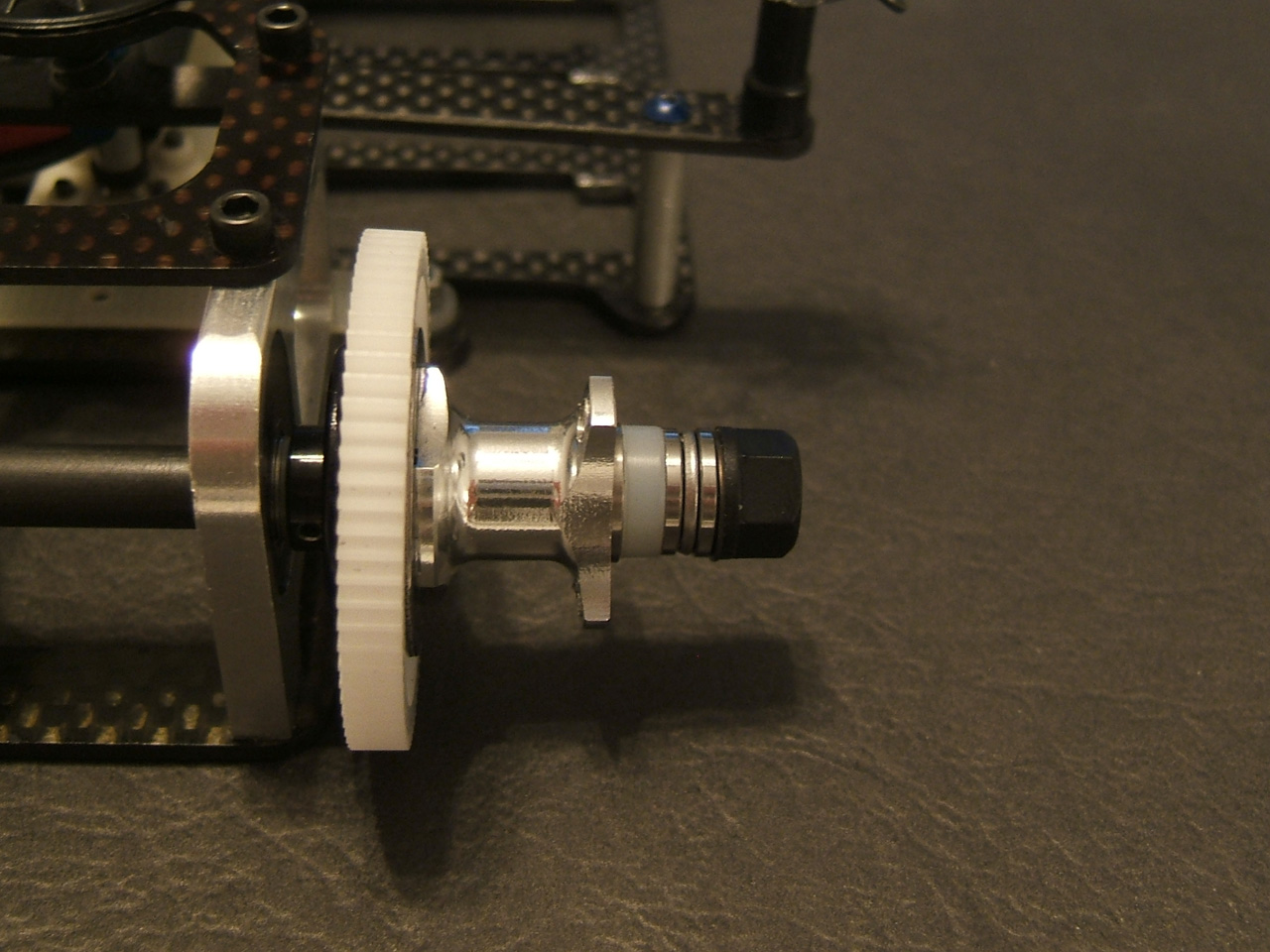
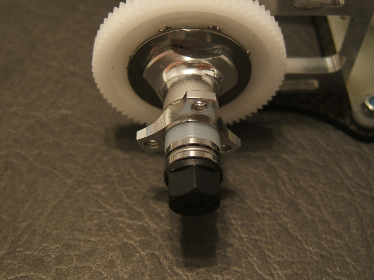
The first picture on the left hand side shows the original spacer (left) and the replacement part (right). The lip on the replacement part is on the outer diameter comparing with the lip on the inner diameter on the original part The second picture (middle one) shows the thrust bearing with some appropriate grease for this item (see items purchased above for reference). The amount of grease is largely not enough, the quantity need to be doubled at least. The third image (right hand side) depictures the order of assembly: spacer, thrust bearing, Belleville spring and nut. Both spacer and thrust bearing are not centered along the axle and need to be carefully positioned when the nut will be tightened. If they are not centered when fully mounted, the right wheel couldn't be position correctly. To have a co-axial assembly, use a wheel, tight the nut, remove the wheel and visually check if the whole package do not wobble during the rotation of the axle. Both pictures below show the thrust bearing in position with the adequate spacer. |
 |
 |
Chassis preparationThe first step was put all parts tougher and the following pictures show the result without the thrust bearing. The assembly is straight forward, adjusted with four shims, two on each side on first instance. The number of shim is a setup parameter as that will wider or narrower the rear end. To smooth the chassis edges, Team CRC advices were followed as clearly explained on a dedicated page as well as on this website. To proceed, you need, as mentioned on both previous links:
Other than what you can find with both links, here are some additional information:
The following pictures show the result of this process. |
 |
 |
 |
 |
Others changesSome others items were replaced compare with the purchased car.
TipsThe following tip is about electronics installation and particularly servo, its wires and ESC wires. Visible over the internet, there are some very high quality of electronics installation with very clean wires setup as below (pictures from RC Tech). All wires from servo and ESC to receiver are organized on a clean manner. The same apply to the wires going to the batteries and motor. |
 |
 |
|
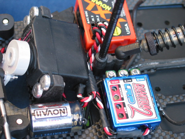
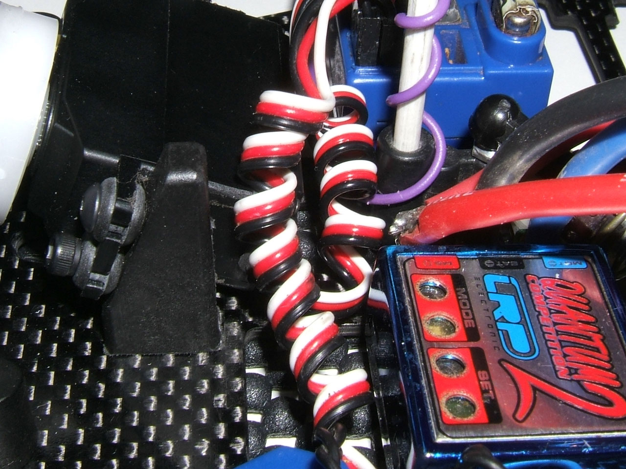
Doing such thing might be a bit long without experience and also experiencing how to do so. The owner saw another solution to setup for his installation. To do so, wrap tight around a wrench (or any 2-3mm axle) the wires as on the picture below. Once done, just remove the wrench, plug it and that won't move. |
 |
 |
 |
|
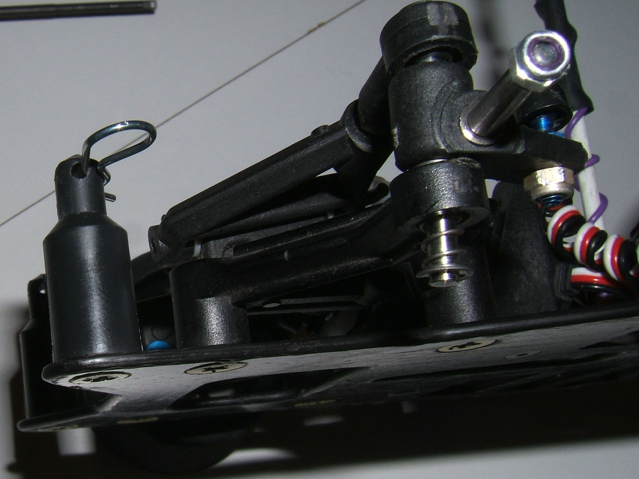
On previous pictures, the servo is mounted on rubber bushes, those bushes won't protect the servo in this case and four 4-40 X 3/8" (or M3) flat head socket screws, as visible the image below, were used. |
 |
 |
|
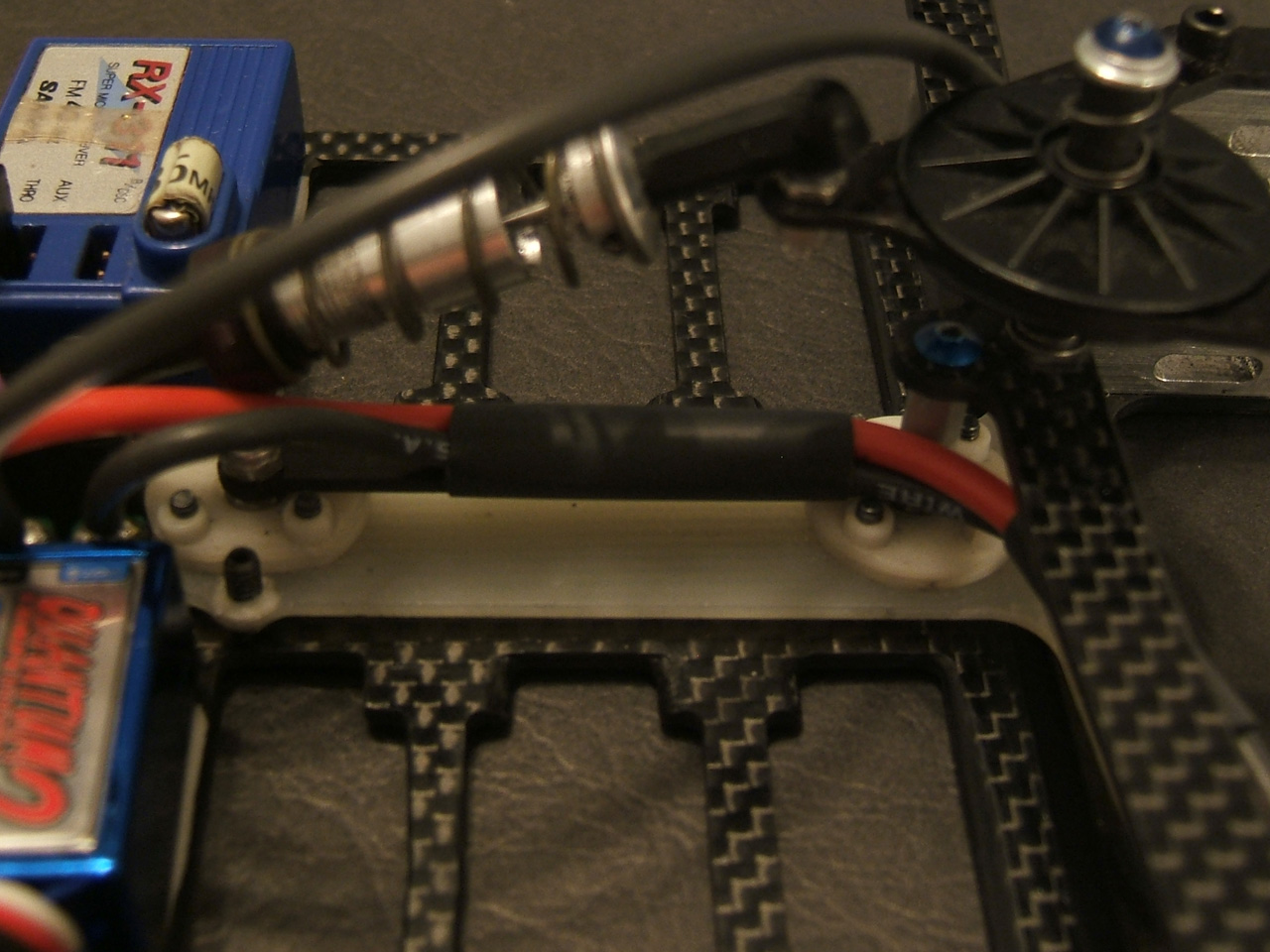
This is not the best option, still better than with the rubber mount, but there is room for improvement. As four screw were used the servo is mounted hyperstatically as it can be seen on the second and third pictures where the upper screw doesn't sit clearly. Two screws is more appropriate and two (the upper ones) screws were removed. The wires dedicated to battery and motor were also set on a relatively net manner. Note the missing red wire need to connect the battery, the picture was taken during the rewiring the ESC. The missing wire will be connect the closest possible to the ESC or soldered on the red wire going to the motor. The wires going to the motor are maintained with heat shrink on the carbon fiber part located above the T-bar. |
 |
 |
|
That all the modifications, update and tips done in this car for instance.
Second part.
|